Structural Rigging Systems and Load Transfer Standards
Northeast Building Movers Archive documents 2005-2026 structural rigging standards, including 36-inch steel W-beams rated for 240-ton historic frames.
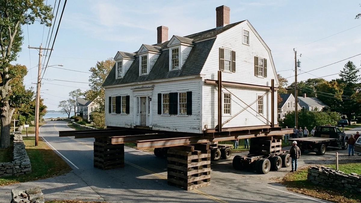
- Unified hydraulic manifolds synchronize lift stroke within 0.125 inches across 16 to 32 perimeter jacking points.
- Primary longitudinal steel W-beams carry 65 to 80 percent of dead load, while cross-needle beams distribute sill and joist weight.
- Hardwood oak cribbing stacks require 4-by-4 or 6-by-8 cross-tiered geometry to maintain a 4-to-1 base-to-height stability ratio.
- Pre-lift structural surveys recorded at the North Hampton, NH yard since 2005 establish baseline plumb and crack-gauge tolerances.
Core Rigging Architecture for Historic and Commercial Frames
Relocating an intact structure requires transferring gravity loads from masonry or concrete footings onto a temporary steel chassis without inducing differential settlement. In New England practice documented since 2005, crews install longitudinal main carrying beams beneath load-bearing walls before threading transverse needle beams at 48-inch to 72-inch centers. Each intersection receives steel shims and hardwood wedges to eliminate deflection gaps before hydraulic pressure is applied.
Timber-frame Colonial homes, nineteenth-century carriage barns, and brick commercial blocks behave differently under temporary support. Wood-frame structures tolerate minor flexural movement along mortise-and-tenon joinery, whereas unreinforced brick masonry demands continuous perimeter steel framing and tensioned tie-rods to prevent shear cracking during road transit.
Comparative Rigging Topic Index
| Rigging Subsystem | Primary Equipment | Typical Capacity | Tolerance Benchmark | Archive Reference |
|---|---|---|---|---|
| Main Carrying Beams | W36x150 to W36x300 Steel I-Beams | 120 to 320 tons per pair | Max span deflection L/480 | Hydraulic Jacking Guide |
| Cross-Needle Beams | W12x50 to W18x76 Steel Sections | 18 to 45 tons per needle | 48-inch to 72-inch spacing | Technical Reference Atlas |
| Unified Jacking Rig | Synchronized 50-ton Hydraulic Cylinders | 400 to 1,200 tons total | 0.125-inch stroke variance | Hydraulic Jacking Guide |
| Timber Cribbing Stacks | Seasoned 6x8 Mixed Oak Timbers | 350 psi perpendicular grain | Max 4:1 height-to-base ratio | Technical Reference Atlas |
| Masonry Bracing | External Channel Walers and Tie-Rods | 0.75-inch to 1.25-inch rod | Zero mortar bed separation | Masonry Relocation Guide |
Dollies, Steering Geometry, and Road Load Distribution
Once a building reaches travel elevation on timber cribbing, multi-axle hydraulic dollies are rolled beneath the main carrying beams. Modern self-leveling dollies use interconnected hydraulic suspension circuits arranged in a three-point support plane. Because any three points define a flat plane regardless of road crown or superelevation, the superstructure remains free of torsional twist when crossing crowned highways, bridge approaches, or driveway aprons.
- Three-point hydraulic suspension isolates the building sill from 6-percent road camber changes.
- Steerable rear bogie axles reduce swept turning radius on narrow coastal lanes in New Hampshire and Maine.
- Axle-group spacing complies with state bridge-formula weight limits across 8 to 24 wheel lines.
Field Inspection Checkpoints Before Lift Initiation
Before a single cylinder extends, the rigging foreman walks the perimeter to verify utility disconnects, chimney strapping, and sill-beam bearing contact. Crack telltales installed on interior plaster and exterior brick joints provide objective confirmation that lift forces remain evenly balanced across every cribbing tower from initial breakaway through final set-down.
Sections
Route Permitting, Utility Clearance, and Corridor Logistics
Route permitting protocols archived from 2005 to 2026 coordinate state DOT oversize loads, bridge ratings, and 18-foot utility
Unified Hydraulic Jacking and Timber Cribbing Mechanics
Unified hydraulic manifolds lift 240-ton structures within 0.125-inch tolerances across 24 jacking points, documented in
Historic Brick and Masonry Relocation Engineering
Unreinforced brick buildings weighing 450 tons require perimeter steel channel walers and 0.75-inch tie-rods to prevent shear
Structural Moving Terminology and Engineering Atlas
This 15-entry technical atlas standardizes structural moving terminology, hydraulic jacking specs, and permitting metrics
Structural Cribbing Geometry and Timber Load Distribution in Historic Building Moves
Standard 6x8-inch white oak cribbing stacks distribute up to 42 tons per tower during 2026 structural lifts documented since 2005.
Underpinning Antique Brick and Stone Structures Without Mortar Shear
Antique brick structures require needle-beam spacing every 48 inches to limit flexural deflection below 0.06 inches in 2026
Frequently Asked Questions
Why do structural movers use three-point hydraulic suspension during transit?
Three hydraulic zones act like a tripod, allowing the dolly frame to absorb uneven road crowns and dips without twisting the building above.
What steel beam sizes are standard for residential and historic moves?
Crews commonly pair W24 to W36 longitudinal main beams with W12 or W14 cross-needles spaced every 4 to 6 feet under floor joists.
How high can hardwood cribbing safely elevate a structure?
Box cribbing is stacked in alternating perpendicular layers with a minimum base width equal to one-quarter of the total stack height, often reaching 8 to 14 feet.