Unified Hydraulic Manifold Control and Precision Structural Lifting
Unified hydraulic manifolds synchronize up to 24 lifting cylinders within 0.05 inches of elevation variance during 2026 structural raises.
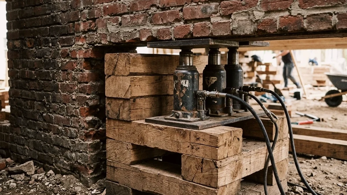
- Unified hydraulic jacking links multiple cylinders to a central diesel or electric power pack divided into balanced flow zones.
- Three-point hydraulic zoning prevents torsional twisting by allowing each corner zone to level independently.
- Pressure gauges reveal real-time weight distribution across steel main beams, exposing hidden point loads immediately.
- Mechanical safety lock-nuts on threaded cylinder rams provide positive fail-safe support during every cribbing cycle.
From Manual Screw Jacks to Unified Hydraulic Manifolds
Early twentieth-century house movers raised structures using dozens of manual screw jacks turned in unison by crew members responding to whistle blasts. While effective on small barns, manual jacking carried high risk of uneven elevation on large or irregular floor plans. Modern unified hydraulic jacking systems—adopted across Northeast Building Movers operations since 2005—replace manual guesswork with a single central pump feeding high-pressure 10,000-psi hydraulic hoses routed to 50-ton or 100-ton double-acting cylinders. By controlling fluid flow from a central manifold console, one operator raises an entire 150-ton structure smoothly at 1 inch per minute.
Three-Zone Hydraulic Balancing and Center-of-Gravity Control
A rigid building resting on multiple jacks behaves like a table: if four corners are plumbed to a single open hydraulic line, fluid naturally rushes toward the lightest corner, lifting it faster than the heavy chimney end. To eliminate this instability, unified jacking manifolds group cylinders into three independent hydraulic zones—forming a geometrically stable three-point plane. Each zone has its own needle valve and calibrated analog or digital pressure gauge. By throttling flow to lighter zones while feeding full volume to heavier masonry sections, the manifold operator keeps the entire steel cradle dead level within 0.05 inches across 60-foot spans.
| System Parameter | Standard Spec | Heavy Masonry Spec | Verification Method |
|---|---|---|---|
| Operating Pressure | 6,500 - 8,500 psi | 8,000 - 10,000 psi | Manifold Zone Gauges |
| Cylinder Capacity | 50 tons per point | 100 tons per point | Load Cell Calibration |
| Stroke Length | 12 inches per cycle | 8 inches per cycle | Laser Transit Level |
| Max Elevation Variance | 0.08 inches | 0.05 inches | Rotary Laser & Staff |
Reading Weight Distribution Through Pressure Telemetry
Beyond lifting power, a unified manifold serves as a real-time structural scale. Because hydraulic pressure multiplied by cylinder piston area equals exact force in pounds, reading the zone gauges during initial break-away tells the crew exactly how much each section of the building weighs. If the north wing gauge spikes 1,200 psi higher than architectural estimates predicted, riggers pause immediately to check for an un-severed utility conduit, an anchor bolt missed during foundation separation, or an unexpected stone hearth.
- Pre-lift bleed cycle: Air pockets are purged from all hydraulic lines before applying structural load.
- Split-flow needle valves: Precision metering valves allow micro-adjustments of 0.10 gallons per minute.
- Rotary laser benchmarks: Fixed elevation targets mounted on all four building corners track lift uniformity.
- Burst-rated hose sheathing: Twin-wire braided hoses rated to 40,000 psi burst pressure protect against abrasion.
Synchronized Cribbing Cycles and Controlled Lowering
Because hydraulic cylinders have finite stroke lengths of 8 to 12 inches, raising a building 6 feet onto transport dollies requires repeated jack-and-crib cycles. At the top of each stroke, crews build hardwood box cribbing beneath the main steel beams, verify lock-nuts, and retract the cylinders so timber blocks can be stacked beneath the jacks themselves for the next upward pass. Every cribbing tier is inspected for level seating and full steel-plate contact before transferring dead weight back onto the rams. During final lowering onto a new foundation, pilot-operated check valves prevent sudden drops even if a hose fails, letting the structure settle gently onto fresh mortar beds without shocking interior plaster or window glazing.
The pressure gauge never lies; it tells you where the hidden stone chimney sits and whether every anchor bolt has truly let go before the house rises a quarter inch. — Eddy, Lead Rigging Archive Note, North Hampton, NH
Frequently Asked Questions
Why are unified hydraulic jacks grouped into three zones instead of four?
Three points define a single geometric plane without binding, preventing torsional twist while allowing the operator to level heavy and light sections independently.
What stops a building from dropping if a hydraulic hose leaks during a lift?
Cylinders feature mechanical threaded lock-nut collars that are spun down continuously during lifting, plus pilot-operated check valves that lock fluid inside the cylinder.
How accurately can unified hydraulic systems measure building weight?
By multiplying each zone's calibrated hydraulic pressure reading by the total piston area of its cylinders, crews calculate structural weight within 2 to 3 percent.
Related Archive Dispatches
Further ReadingStructural Rigging Systems and Load Transfer Standards
Northeast Building Movers Archive documents 2005-2026 structural rigging standards, including 36-inch steel W-beams rated for
Route Permitting, Utility Clearance, and Corridor Logistics
Route permitting protocols archived from 2005 to 2026 coordinate state DOT oversize loads, bridge ratings, and 18-foot utility
Unified Hydraulic Jacking and Timber Cribbing Mechanics
Unified hydraulic manifolds lift 240-ton structures within 0.125-inch tolerances across 24 jacking points, documented in