Unified Hydraulic Jacking and Timber Cribbing Mechanics
Unified hydraulic manifolds lift 240-ton structures within 0.125-inch tolerances across 24 jacking points, documented in 2005-2026 field logs.
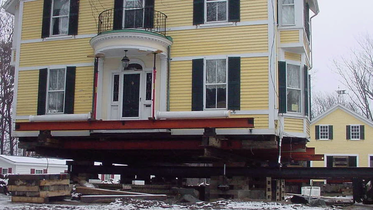
- Closed-loop unified manifolds equalize hydraulic fluid volume rather than pressure alone, preventing uneven lifting on heavy corners.
- Double-acting 50-ton cylinders paired with mechanical lock-nuts safeguard loads during every 6-inch cribbing reset cycle.
- Cross-stacked 6x8 seasoned oak cribbing distributes up to 350 psi perpendicular to grain without crushing.
- Laser water levels and dial gauges verify zero racking across door frames and plaster partitions during elevation.
Why Unified Volume Control Replaced Manual Bottle Jacks
Before unified hydraulic manifolds became standard across New England rigging yards, crews elevated buildings using dozens of independent screw jacks or hand-pumped bottle jacks. Each operator turned a bar or pumped a handle on a foreman's whistle, relying on visual alignment and chalk marks. Even with experienced crews, a heavy chimney corner or slate-roofed wing could lag behind lighter porch framing, inducing diagonal racking in plaster walls and window sashes.
Modern unified jacking machines route hydraulic fluid from a central electric or diesel power pack through calibrated split-flow valves. Instead of allowing fluid to follow the path of least resistance to the lightest corner, flow-divider manifolds meter identical fluid volumes to each zone. As documented in North Hampton rigging logs since 2005, a 24-point unified rig holds elevation variance within 0.125 inches across a 60-foot footprint, even when one corner supports twice the dead weight of the opposite gable.
Cylinder Placement and Steel Needle-Beam Interface
Hydraulic jacks do not push directly against wood sills or stone foundations. Crews excavate or cut access pockets through existing foundation walls to slide longitudinal W30 or W36 steel main beams into position. Transverse needle beams are then threaded perpendicular to the main beams, capturing floor joists, bearing partitions, and masonry piers. Heavy steel spreader plates are placed beneath each jack base to transfer concentrated point loads into compacted gravel or concrete pads.
Where soil bearing capacity drops below 2,500 pounds per square foot, crews lay double-layered 8x12 crane mats or steel road plates beneath the cribbing towers. Spreading a 30-ton tower load across a 16-square-foot mat reduces ground bearing pressure to roughly 3,750 pounds per square foot, preventing the cribbing from punching into wet spring clay.
Step-by-Step Cribbing Geometry and Elevation Cycles
Elevating a structure 8 feet to clear new basement walls or roll-on transport dollies occurs in disciplined 6-inch increments. Cylinders typically have a 10-inch or 12-inch stroke, allowing crews to lift 6 inches, insert a layer of 6x8 oak timbers into the adjacent box cribbing towers, and transfer weight onto the new timber tier before retracting the jacks and resetting them on a higher pedestal.
| Lift Stage | Stroke Increment | Cribbing Configuration | Bearing Check | Target Tolerance |
|---|---|---|---|---|
| Initial Breakaway | 0.5 to 1.0 inch | Base mats and 2-tier oak pad | Verify zero anchor bolts left | 0.06-inch corner variance |
| Sill Clearance | 6.0 inches per cycle | 4-by-4 cross-stacked 6x8 oak | Inspect shim tightness at joists | 0.125-inch plumb check |
| Dolly Roll-Under | 48 to 54 inches total | Wide-base cribbing piers outside track | Confirm main beam flange clearance | 1.5-inch clearance above tires |
| New Foundation Set | Controlled 0.25-inch bleed | Progressive tier removal | Full sill contact on mortar/gasket | Zero daylight under sill plate |
Timber Species, Compression Limits, and Stability Ratios
Not all lumber is suitable for structural cribbing. Softwoods such as spruce or pine compress unpredictably perpendicular to the grain and can split along knots under point loads. Rigging specialists rely on dense, seasoned hardwood—principally red oak, white oak, or beech—milled to uniform 6x8 or 8x8 cross-sections with flat, parallel faces.
- Orient every cribbing layer perpendicular to the tier directly below it to form a rigid interlocking box.
- Maintain a minimum base width equal to 25 percent of total cribbing height (4:1 stability ratio) on level ground.
- Retire any timber exhibiting end splits longer than 6 inches, rot, or crushed edge fibers exceeding 0.25 inches.
- Keep steel-to-steel contact separated by 0.5-inch hardwood crush pads to prevent sudden lateral slipping.
Precision rigging is measured in millimeters at the sill plate, not horsepower at the pump; when steel, oak, and hydraulic flow act as one frame, a two-hundred-year-old house moves without cracking a single pane of glass. -- Northeast Building Movers Field Manual, 2005 Archive
Monitoring Structural Plumb During Descent and Set-Down
Lowering a building onto a newly poured concrete foundation requires the same discipline as lifting it. Masons leave beam pockets in the new perimeter wall so the main steel beams can descend below the top of the concrete, allowing the timber sill plate to rest evenly on sill sealer and anchor bolts. Once the building weight is fully transferred to the cured foundation, crews unbolt the cross-needles, extract the main steel beams through the wall pockets, and mason-fill the remaining openings.
Frequently Asked Questions
How does a unified hydraulic jacking system prevent uneven lifting?
Calibrated flow-divider valves meter equal volumes of hydraulic fluid to each lifting zone, keeping heavy and light corners rising at the exact same rate.
Why is seasoned oak preferred over softwood for building cribbing?
Dense hardwoods like oak resist crushing perpendicular to the grain up to roughly 350 psi and do not split unpredictably under heavy steel beam flanges.
How are the steel main beams removed after the building sits on its new foundation?
Masons leave temporary pockets in the new foundation walls so crews can lower the building onto the sill, unburden the steel, and slide the beams out horizontally.
What is the safe height-to-width ratio for stacked cribbing towers?
Field standards require the base width of a freestanding cribbing stack to be at least one-quarter of its total height, or braced with diagonal tie-backs when taller.
Related Archive Dispatches
Further ReadingStructural Rigging Systems and Load Transfer Standards
Northeast Building Movers Archive documents 2005-2026 structural rigging standards, including 36-inch steel W-beams rated for
Route Permitting, Utility Clearance, and Corridor Logistics
Route permitting protocols archived from 2005 to 2026 coordinate state DOT oversize loads, bridge ratings, and 18-foot utility
Historic Brick and Masonry Relocation Engineering
Unreinforced brick buildings weighing 450 tons require perimeter steel channel walers and 0.75-inch tie-rods to prevent shear